FLWO 48" INCH TELESCOPE REALUMINIZING PROCEDURE
Updated 08/23/17 EF
Items needed:
Notify SO and confirm that schedule is OK.
Sign Agreement and forward to SO.
Issue PO for the work.
Aluminum mirror lifting device
Yellow bar
Yellow hoisting tool
Yellow 3-legged cart
Mirror box and lid
Plastic tarps to cover mirror box and cell in case of rain
Foam mirror cover
Crown forklift
Pallet jack
2 short lifting straps
Mechanical Hoist
Removal Procedure
-
Remove Dec primary bearing cover (East fork).
-
Move telescope in DEC only, South to ~0 DEC so that access to the
Eastern cell bolts (particularly the southernmost of the three) can be
had. Loosen the two bolts. This is done because these bolts can't be
fully accessed when telescope is at zenith. Don't even try.
Even more complicated if the topbox has been removed.
On 07/25/12,
we had the topbox off after the rain event on Sunday 07/15/12
(see Changelog). Ted managed to remove the middle bolt with the
telescope pinned. We managed to slowly and
carefully move the telescope after
removing the DEC pin using ropes and pulleys tied to the
OSS on the N and S with Wayne, Ted and
Emilio handling the ropes. The remaining problem bolt on the N end
of the trio finally became accessible and was removed.
-
Return telescope to zenith.
-
Pin telescope at zenith.
-
Bring secondary mirror all the way toward primary (larger numbers
for the hexapod) with the telescope control program. From code
or hexapod PC:
Range -24 to +24 mm, so move to 23.0
-
If filter wheel assembly requires work: remove all filters
from top box, using TCS. Then, move all guide
probe motors to 0 using TCS and disconnect motor power.
-
Power off topbox and Lakeshore. Remove instrument and cabling
carefully, to avoid straining any wires. Disconnect cabling to
topbox.
-
Remove any interfering wiring from North plate electronics.
-
While standing on closed mirror doors, remove secondary baffle, 4
3/32" Phillips screws.
-
Remove secondary mirror. This is a
two-person job on top of the telescope!
First, remove felt on center of secondary.
Second, insert all-thread safety bar through the center of the support
and secure it with the nut (which should be on the bar when in
storage) below the secondary. Third, remove the 4 allen screws
(3/16") that hold
the mirror mushroom against the hexapod; the mirror is held by the bar at
that point. Fourth, one person should hold the mirror by the collar
while the other loosens the nut on the bar, and then carefully lower
it and hand it to a third person at the top of the yellow ladder.
-
After the secondary is moved to the hole in the center of the wooden
(dewar) cart with the mirror facing up, remove secondary mirror mount
by removing the 6 allen screws (3/32", of slightly different lengths)
that hold the washers (spring and teflon) on at the front.
From below the hole, remove the 3 allen
screws (9/64") that tie the holding fixture to the metal puck on the
back of the mirror. No need to remove the collar!
Then, gently twist the "mushroom" with respect to
the mount until it is twisted off. It can take some doing as it's a VERY
snug fit. There are 2 o-rings on the shaft, 1" OD, that may break during
removal. We are ordering some of these 8/17/17.
-
Place secondary mirror in its box for shipping (replacing the second
secondary mirror, which is stored on a shelf, in the cabinet
inside the clean room).
-
Remove topbox. Raise the lifting table to the level of the topbox,
and then remove the bolts that hold the spacer plate onto the cell.
-
Remove the primary baffle. It has a ring where the mirror covers rest,
so it is best to do it at this point, not earlier.
-
Remove cell cover plates.
-
Raise the 3 axial hardpoints. Give each one 1.5 turns. At
that point, the primary will be
fully supported by the hardpoints. This procedure
deactivates the 27 axial actuators, which need not be touched so
at re-assembly, the primary will return to its position before removal.
-
Install yellow bar at top ring using two short yellow straps around
the top ring and around the OSS arms.
Bar should be aligned north/south. One person should
remain on top of the primary covers to work with the hoist.
-
Install mechanical chain hoist. The chain is too long and heavy.
Larry will shorten the chain (8/1/17).
-
Bring chain down through the Cass hole, and hook it onto the yellow
hoisting tool (flange with stem, aka mushroom).
-
Raise hoisting tool to bottom of mirror cell. Bolt tool to cell (2
bolts will do). Tighten up chain.
-
Loosen and remove cell bolts. Note that the northernmost bolt on the East
side is shorter than the others. The cell is made of 1018 HRS; it
weighs about 1040lb.
-
Lower cell onto the 3-legged cart, until it rests on the
legs but without engaging the legs in the holes to lift the mirror. Be
careful of cell/telescope clearances.
Mind the gap! Between the dial indicator on the NE side and the E
side cover. It is all too easy to bend the indicator and make it useless.
-
Working above the mirror, remove the earthquake/baffle ring.
Remove the piece with angled ends first.
-
Remove the radial dial indicators (these are labeled, keyed to
the same labels on the cell). If not exactly at 0, reset them all to 0 to
simplify centering during reinstallation. Make sure to leave the indicators
undisturbed, so they will read useful numbers at reinstallation.
-
Disengage the radial actuators from the invar radial load spreader
bars. As of August 2013, we have new spreader bars (made at UA's
University Research Instrumentation Center, URIC) on the new mirror.
Posts were epoxied to the glass with Hysol 9313 (mounted at COS
following Joe Zajac's instructions).
They are much sturdier than the old ones, but a bump could pry them off.
In August 2014, we easily removed the pins that link the
actuators to the bars, after removing the cotters at the ends of the
pins.
- Remove the radial actuators.
Unscrew only the 4 hex (3/32) screws so the actuators
will maintain their position relative to the cell at reinstallation.
-
Back off the radial hardpoints until you see about a 2mm clearance.
-
Lift the cell off the 3-legged cart a few inches, and align the legs with
the holes in the cell that will permit contact with the mirror.
Larry replaced all 3 wheels of the cart with wheels that swivel.
Much better!
-
Lower the cell onto the cart, until it makes contact with the glass.
This is a good time to pop some of
the 3 delrin 1/2
pucks
off the bottom of the cell, working from below
the cell. Only pop the 3 1/2 pucks that let temp sensor wires through.
Pull through the temp sensor wires, one connector at a time.
At that point, the wires should rest on the cell so as not to impede
the removal of the primary.
-
Slowly lower the cell until the mirror is about
2 inches above the cell.
Always watch the temp sensor wires so they don't get
tangled, pulled, or pinched.
-
Install the aluminum triangular mirror lifting fixture using
3 straps from the eyehooks to the hook on the chain. Lift the mirror
off the 3-legged cart.
-
Remove the radial load spreader bars from the mirror (these
are numbered and keyed to the same numbers on the mirror).
-
Roll the cell out of the way. Take care not to run a wheel over a trench
where the floor is weak.
-
Open the box, remove top foam padding, and use the pallet jack to roll
it under the mirror.
-
Lower the mirror into the box.
-
Remove the lifting fixture
-
Put the top on the box.
-
The mirror box is 64"x64"x 19". The 19" includes the blocks on the
bottom to provide fork lift access. The box weighs 550 lb. The new
mirror weighs 430 lb.
-
Load the mirror box in the flat bed truck. The Crown 15M hand forklift
will lift 1500 lb at 20" . There is a chance that the mirror box could
tip forward, therefore, the mirror box should be attached to the fork lift
with a harness. The height of the loading dock is 25" from the drive. Lady's
bed is 40" from the drive. The front part of the mirror box is first set
in the truck and then the mirror box is pushed in with the fork lift and
people. This works better than it sounds.
-
No special padding is required. Drive flat bed truck to Sunnyside.
Reinstallation Procedure
In general, the reverse of removal. The following notes may be useful.
When lifting the box from the truck and moving into the dome, be certain
that the 4x4's on the box clear the front fork wheels as well as the forks.
-
If the secondary was aluminized, reverse the disassembly procedure.
To re-install the secondary mirror mount,
first place the teflon washer over the hole.
Then, screw in the 6 allen screws (3/32", of slightly different lengths)
that hold the washers (spring and teflon). Start one of the longer
screws first, to locate the hole for the screw. Then, proceed with
the other screws.
- If some of the temperature sensors fell out, be ready to have
fun with epoxy (Omegabond 101, in the fridge). Lower the mirror on 3
3-ft 4x4s (in the chamber). Leave the mirror hanging on the triangular
lifting tool, apply partial weight on the 4x4s. Proceed to gluing.
The extensible back scratchers that prop up the
epoxied sensors are stored in the red tool box,
top section, in the shop. Working from below,
apply Omegabond to the each sensor, and
use the back scratchers to push each sensor against the glass, inside
the honeycomb cells.
Use one small section of 4x4 and a wedge to help stand up the back scratchers.
The Omegabond needs to cure overnight.
We will look into using thermally conductive tape next time.
- Mount spreader bars on mirror before installing the mirror in
cell. As of August 2013, the new posts are symmetrically arranged
on the new mirror,
so there is no need to offset the bars as for the old mirror.
The spreader bars are mounted
to the posts with, starting at the post, a plastic washer, 2 cupped
bellevilles, the bar, 2 cupped bellevilles, a nut. Per DFM
instructions on 08/07/13.
- Radial dial indicators should already be
out (see removal procedure above). If not, remove them now.
- Lift the mirror off the 4x4s. Roll the cell underneath the mirror.
Lower the mirror until it rests on the nylon pads of the 3-legged tool.
Carefully feed the temp sensor wires through cell holes (3 with 1/2 pucks,
one just a vent hole),
and reinstall the 1/2 pucks (push them down with some
force). Use tie wraps to bundle the wires near the mirror, and attach
bundles to the cell with tie wraps through the pads on the cell.
- Get rotation correct before lowering mirror all the way into cell. Now
lower mirror onto axial hardpoints, which were raised 1.5
turns during removal.
RH made a jig (see pics
below) that allows mounting a dial indicator at either end. It's stored
in the shop, in the top section of the red tool box.
If necessary, use it to measure
the separation between the outer circumference of the
cell flange and the side of the mirror or the
separation between the edge of the mirror and the top of the
cell flange.
- Lift the mirror and cell at least 1ft higher than when
it was resting on the 3-legged tool for the load cell connector to
reach the socket in the cell. The primary should now rest on the axial
hardpoints giving load cell readings of around
120 lb. If lower than this, the mirror may be stuck on something.
- Lower the
axial hardpoints by removing the 1.5 turns described in the removal procedure.
The primary will then rest on both the axial hardpoints and
the nylon pads. Reset the axial
dial indicators.
- Height of mirror: Edge of mirror should be 1.25 inches below
cell mounting flange. Check (and re-check) level
from top surface using the RH jig.
- If they were disengaged, re-engage
axial actuators before doing final centering, to allow ease of motion.
- Move mirror radially using the radial hard points, monitor the
re-installed dial indicators for motion. Hard points are quite springy,
so some relaxation must occur before taking readings.
- Mount the 6 radial actuators. For these, the bearing that attaches to
each bar has two nuts. These must allow some play when attached to the bars.
- Remember to install short bolt rightmost (N) of the three
holes on the East side.
Only two bolts are installed on this side (middle and rightmost). Put these
two in with fingers first, then when telescope is movable, move telescope
far south so that a wrench may be used for final tightening.
-
Reinstallation of the secondary mirror is a
two-person job on top of the telescope! Plus a third person on the tall
yellow ladder. Reverse the removal procedure.
- Adjustment of the axial actuators is a many-iteration process. Monitor
the axial loads as you work around the counterweights. Start by lowering the
radial hardpoints until you are close to the final load on each hardpoint,
about 21 lb. The axial counterweights should move freely up when pushed,
about 1 inch until they hit the cell. Some of these may become pinned
to the cell. Ease these out by unscrewing the larger bolt at the pivot
end of each counterweight. If the bolt comes out, the pin will fall
through and the puck will end up lying on the cell. Most of the
pucks are inaccessible with the mirror in the cell. Once all the
axial counterweights are free to move, and the axial load cell readings
are about 21 lb, you are done. However, when the top box is mounted,
all these readings will change and will require re-adjustments. About
1/2 of the counterweighs are inacessible with the topbox mounted, and
only the S hardpoint hole is accessible.
Fun visual notes for the reinstallation:
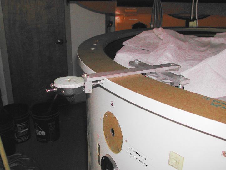 RH jig in the mode used to measure the primary centering in the cell.
The cell flange OD is 58 inches (from
DFM drawing). The mirror is 48 inches, the difference
is 10 inches, so 5 inch for the spacing between the
outer edge of the flange and the mirror edge. The latest reading (9/17/15)
with the jig was 303 +- 3 x 0.001 inches (measured at 4
cardinal points), a relative number that
indicates centering good to +- 0.003 inches.
RH jig in the mode used to measure the primary centering in the cell.
The cell flange OD is 58 inches (from
DFM drawing). The mirror is 48 inches, the difference
is 10 inches, so 5 inch for the spacing between the
outer edge of the flange and the mirror edge. The latest reading (9/17/15)
with the jig was 303 +- 3 x 0.001 inches (measured at 4
cardinal points), a relative number that
indicates centering good to +- 0.003 inches.
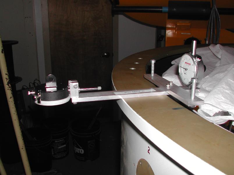
RH jig in the mode to measure the primary depth in the cell.
Should be 1.25 in.
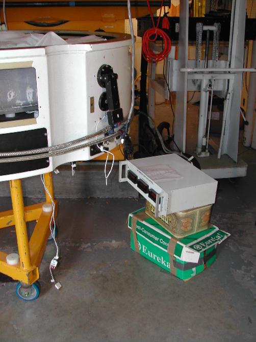
Reading out load cells with cell on 3-legged cart.
********************************
REALUMINIZATION 2004 (KPNO)
********************************
REINSTALLATION NOTES 2013(pdf scans)
REINSTALLATION NOTES 2014
REINSTALLATION NOTES 2015
REINSTALLATION NOTES 2017